Category: Woodworking

Shield v.2 – Finished

Testing straps for the shield handle

Testing straps for the shield handle

Water-softened rawhide edging held in place with binder clips

Water-softened rawhide edging held in place with binder clips

Carpet tacks used to hold ends of edging

Carpet tacks used to hold ends of edging

shield4

Saddle stitching with waxed linen thread

Completed hardware including leather-wrapped foam pad

Completed hardware including leather-wrapped foam pad

Finished shield front

Finished shield front

Shield v.2 – Shield Press

I never expected my first heater shield to be my Forever Shield, so it’s no surprise that I’m making a new one. At the regional fighter practice, I was informed by a knight of great wisdom and experience that I was using the wrong shield for me. After borrowing his shield for a few fights, I was convinced that he was right and decided to take his advice.

The plan for the new shield is a 22″ x 32″ heater (vs ~24″ x 28″ for the old one) with a ~1/5″ curve. This website has some neat ideas that I plan to pilfer, and I found some nice instructions on rawhide edging here. The first step is to construct the body of the shield.

shield-press-1

I didn’t want to spend too much money or effort on building the shield press, so I made this frame out of 2×4’s screwed together.

shield-press-2

I cut two pieces of 1/4″ birch plywood roughly 24″ x 36″ so I had enough space to trim things up when I was done. Both pieces were liberally coated with wood glue.

shield-press-3

I drew the shape of the shield is drawn on the inside layer, then put the two together on the frame. Another 2×4 and a pair of wood clamps provided the pressure for the glue and the curvature.


shield-press-4

I cranked the clamps down on either end until I had about the curve I wanted. Now I’ll let it sit for a few days to dry and hope that it turns out.


Folding Trestle Table: Trestle v2.0

The original folding trestle table was a quick proof of concept, which did the job of showing how the thing worked. Unburdened by reckless eagerness, I put in some proper shop time to make a nicer version. This one was made to the same dimensions out of some oak reclaimed from an unknown past project. The construction is all mortise and tenon (with liberal use of power tools), but otherwise has the same form as the first one. I applied two coats of spar varnish while the two frames were still separate. To allow for this, the hinge this time involved a hole through the full width of the inside frame and another halfway through the outside frame. The inner hole is exactly 3/8″ to allow for the hinge pin to have a snug fit, while the outer hole is 1/64″ larger so the hinge can move freely.

The only part that is visibly different in form is the ring/hook hardware for the adjustment chains. The description of the example in the V&A is fairly informative, though there is no picture of this feature:

Two iron chains (of 13 long links) are fixed to one upper stretcher on rings, any link of the chain fitting over an iron hook in the opposite upper stretcher, so as to secure the trestle open and adjust the table height. The two hooks and rings are driven through the stretchers and the split ends bent over.

To approximate this arrangement, I again made use of the ever-present coat hangers, in a slightly more complex manner.

Red Oak Casket

I built another casket out of red oak, using mostly the same techniques that were used on the pine casket. Rather than make a bunch of posts that are essentially identical to the last set, I collected a gallery of progress photos on its project page.

Casket: Finished

The only things left to do are adding the handle and applying the finish. First, the handle:

The handle is made from the same round stock as the lock bolt, bent to shape. I tried making fancy ends, but that didn’t really work out so I opted for a more minimalist look. The brackets are strips of steel formed by folding around a piece of round bar and then clamping in the vise.

I marked the slots on the lid, drilled a few holes and cleaned out the rest with a chip carving knife.

The handle hardware was blackened using the same process as the rest of the metal. The handle itself got two coats of oil.

The handle assembly ready to be installed.

A few taps with a rubber mallet did the trick nicely.

Here you can see the ends of the brackets on the bottom side of the lid.

I spread the ends of the brackets by levering them apart with an old chisel, then did most of the bending by hand. A couple of hammer taps finished the job.

The last thing to do was applying a coat of boiled linseed oil to the whole box, inside and out, wood and metal. I plan to do a couple more coats later, but I think this is pretty much the final appearance. This was, as usual, a very enjoyable project. It’s always nice to see a complex object that began as very simple raw materials.

Casket: Main Construction

With the lock installed and functioning, the next step was to actually build the box.

The sides of the box were put together with wood glue and clamps. I thought about putting some extra nails in the corners that would be hidden by the straps, but it seemed like overkill. Also, I didn’t want to risk splitting the edges of any of the boards.

Here’s a shot of the front with the corner straps and bottom attached. Due to the aforementioned splitting worries (I don’t have any of this wood left to replace broken boards), I drilled pilot holes for each nail about halfway through the thickness of the wood. I also did most of the nailing with the boards supported by the horn of the anvil, or on the face when I could. All the hardware was blackened using the same method as the lock cover, but with only one coat of oil.

The bottom was attached with glue and thoroughly modern looking finishing nails. I wanted to make sure I could put this box down on a table without worrying about it scratching anything, so this seemed like the best option. The bottom board had the most cracks in it (and in fact broke in half at one point and needed to be glued back together), so I put it in the position where it would be the most supported.

A close up of the corner straps. I marked the front and back boards to make sure the straps were at the right height, but each had to be positioned individually since they were nowhere near identical.

One of the hinges. The quatrefoils aren’t quite evenly spaced, but they are consistent between the three straps. I experimented with a scalloped edge at the end of the straps, but it didn’t seem to be worth the effort, and might not have looked very balanced.

After getting the lock in place, it turned out that my original hasp wasn’t going to line up with the slot like it needed to. Fortunately, hasps with this sort of dog-leg are quite common. I cut a new one and kept on truckin’.

Laying out the first hinge strap. Here you can see the notches I had to cut in the box lid to accommodate the hardware. Not an ideal solution, but the best I could do.

Here are the hinges fully installed. This is one of my favorite pictures. The position of the hinges meant the straps on the back overlapped the ends of the corner straps. This is pretty common in period examples, and I’m glad I didn’t try to avoid it (to be perfectly honest, it didn’t even occur to me that this might happen until it did).

This was the first version of the staple for the hasp. The final one was just about the same shape, but made form a thin strip of sheet instead of a flattened coat hanger. The coat hanger ended up being too hard and brittle to make all the sharp bends I needed.

Here is the final version of the hasp. I had to tinker with the shape and position of the staple quite a bit to get it to engage the bolt properly, but it seems to have ended up working fine. The ends are simply bent back toward the center on the other side and crimped down.

All that’s left to do is fabricate and install the handle and give it a linseed oil finish. Here are some pics of the (nearly) complete casket:

Casket: Lock v.2.0

The first version of the lock was not very elegant, and the key kept catching on the corners of the brackets, so I revised my plan.

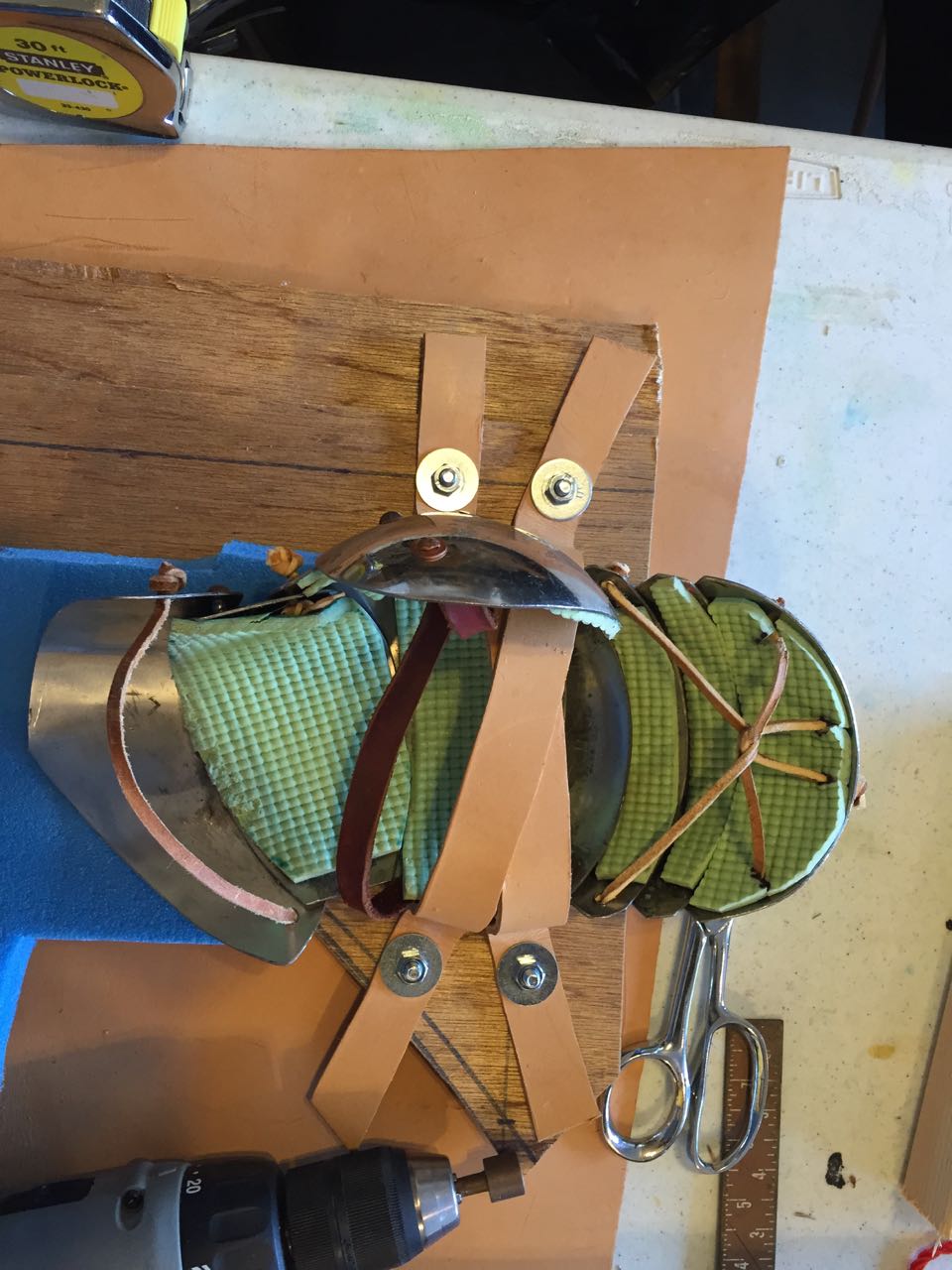
Here you can see the main mechanism of the new lock. Instead of two brackets, there is one bracket with rectangular holes on either end. This makes it easier to clear the path of the key, though it does have other issues that will be seen later. I had originally planned to use the same leaf spring design as the v.1.0 lock, but after going back to look at my source images I decided to try attacking the spring to one of the bracket flanges instead. While the theory was sound, the piece of brass shown here did not have sufficient stiffness to maintain good tension.

This is the paper template for the lock cover, including placement of the keyhole and the slot where the hasp will connect to the bolt.

Here is the paper template placed over the lock mechanism. You can see the bolt in the locked position inside the slot.


This is v.2.1 of the lock mechanism. The problem with the v.1.0 leaf spring was that the piece of hair barrette I was using was too narrow to properly engage the bolt (and also hard to attach). The solution, therefore, was a wider barrette. A quick trip to the dollar store got me a 6-pack of nice flat barrettes of various widths. The previous orientation of the brass spring didn’t work with the stiffer steel, so I flipped it upside down and bent it to where it needed to be. Bending the spring had to be done very carefully, as it breaks easily if bent too sharply.


This is a closer shot showing the attachment of the spring. I had a problem later with the bolt, after the cover was in place. While the bolt was prevented from going too far to the right by the side of the lock cover, there was really nothing to prevent it going too far to the left from an over-enthusiastic turn of the key or vibration from hammering. There is no sound quite as depressing as a bolt rattling around loose inside a nailed-on lock. I had to pull out nails (twice) to fix a wayward bolt. In the end I put the bolt in the vise and mushroomed the right end of it slightly so it would no longer be able to fit through the hole in the bracket. Problem solved!

Here is the lock cover cut out of the same steel as the rest of the hardware and bent into shape. It took some finagling to get everything going the right way, but it all turned out in the end.

Since I wanted to mount the lock on the front of the box before it was fully assembled, that meant the lock cover was the first piece that needed to be blackened. I placed the cover on a piece of fire brick on top of the anvil and heated it with a propane torch. Once it was hot enough that black oxide appeared on the surface, I picked it up with a specialized tool (coat hanger with one end bent into a hook) and dunked it in a metal bowl of safflower oil. I removed it from the oil, let most of it drip off, then put it back on the fire brick to heat it again. This process was repeated one more time just to be sure. I also had to go back and re-treat the edges later after I dinged it up trying to pull out nails.


Here you can see the lock mechanism ready to be mounted to the front board of the box. The center point of the board is marked in pencil, but the lock mechanism is offset slightly relative to the cover. You can also see the hole drilled for the post of the key.

The lock mechanism nailed in place. These are 9/16″ black cut nails that I found at Lowe’s for super cheap. They hold well and look good, so I ended up using them for all the construction of this box (with one exception).

The completed lock installed. I did not, in fact, ever check to make sure the lock cover would fit on the front of the box. I could have cut off the top and/or bottom flanges to make it fit if I needed to, but I got lucky and was able to squeeze it in as is. Once the cover was in place, it turned out that I had to file down the bit of the key just a smidge to make sure it cleared everything inside. Next time, the actual construction of the box!

Casket: Copper Rivets

The lock is held together with several tiny copper rivets. Here’s a little tutorial on how I made them.

I start out with a piece of copper wire clamped tightly in a pair of vise grips. There’s about 1/8″ extending above the jaws.

I set the vise grips on top of a vise that’s open just enough so that any extra wire can fit between the jaws. A piece of scrap steel with a hole drilled in it is placed over the wire so that I have a nice flat surface to work with.

The exposed end of the wire is peened to create a head for the rivet. Sometimes the wire below bends a little and needs to be straightened back out.

The rivet is cut to length with flush cutters. This is one of the points where I am most likely to lose the rivet.

If the rivet is in an easily accessible spot, I can peen the other side on the anvil. Most likely, especially when building locks, the is not the case. I use a large nail set clamped in the vise as an anvil. It allows me to support rivets in awkward places, and also gives a nice round shape to the head.

Here the rivet is placed in the hole. This is the other point where I am likely to lose it. Needlenose pliers and patience are very useful here. You can see how much stuff there is to work around on the front side of the lock; this is where the nail set comes in very handy.

And here are the rivets in place. Not the prettiest, but quite effective. When I went to replace this brass leaf spring, I had to grind the rivet out with the Dremel.

Casket: Lock v.1.0

Back when I was figuring out how to build locks before, I found this lovely resource that got me going in the right direction. This first version of the lock mechanism is based on what I recall doing last time, but I don’t think it’s the way I’ll be going in the end. Still, it was a good exercise.

So here we have the key I bought. In the past I cut the bit down on my keys, but this one is small enough that I plan to leave it intact. I hate to cut up old things if I don’t have to, so this makes me happy.

Here I have the back plate of the lock mechanism, with a hole drilled for the post of the key going all the way into the board behind so the key will go in to just the right depth and remain stable. The plate is a piece of stainless cut from leftover bits of the toaster over shell I used for my Jedi belt.

I secured the back plate temporarily with carpet tacks, and marked out the path of the key.

I left the steel rod I planned to use at my parents’ house, but fortunately I had another one lying around. It was a bit smaller, but actually not a bad size for what I needed. I flattened it into a rectangular cross section on the anvil.

A bit of filing made a serviceable notch in the bolt.

I cut a couple of brackets to hold the bolt, and tacked them in place to test them.

A couple more tacks and a piece of a hair clip made a tension spring. You can also see a piece of cardboard behind the bolt serving as a spacer, so there will be room for the hasp to go around the bolt.

The brackets are permanently secured using small pieces of copper wire as rivets.

Here is a metal spacer riveted in place behind the brackets.

While this lock would probably work, it is awfully fiddly and was not the easiest thing to fabricate. I have another method that I plan to try soon…

Casket: Boards and a Dilemma

The other part of the project that I accomplished last weekend was cutting the boards for the box. That part went fairly smoothly. I got my hands on a piece of reclaimed heart pine, planed it down to 1/2″, and worked around the various cracks, knots, and holes to get a set of boards for my box. The top and bottom had an extra bit of overhang that I prettied up with the help of a router.

Nothing is actually attached yet, but it looks pretty good so far. Unfortunately, I took a closer look at my primary inspiration (seen here from the back) and saw a problem. My original interpretation was that the hinge went under the lid, with a separate metal piece on top and nails going through everything. A second look, however, made it clear that the hinge only goes under the nailed-on border on the edge of the lid, and is attached right to the top of the lid itself. Unfortunately, the fancy border of the lid I made doesn’t really lend itself easily to this construction method.

I’ve found at least one instance with a similar lid where the hinges seem to just be nailed on from below, but that would leave me with a boring, unadorned lid. Fortunately, I found another example with an oversized lid where the edge was simply cut away to make room for the straps of the hinges and hasp. This is probably the way I’m going to go.